
Load Testing Drilled Shafts: Proving What the Design Assumed
March 6, 2026 · 7 min read · By Thomas Charles
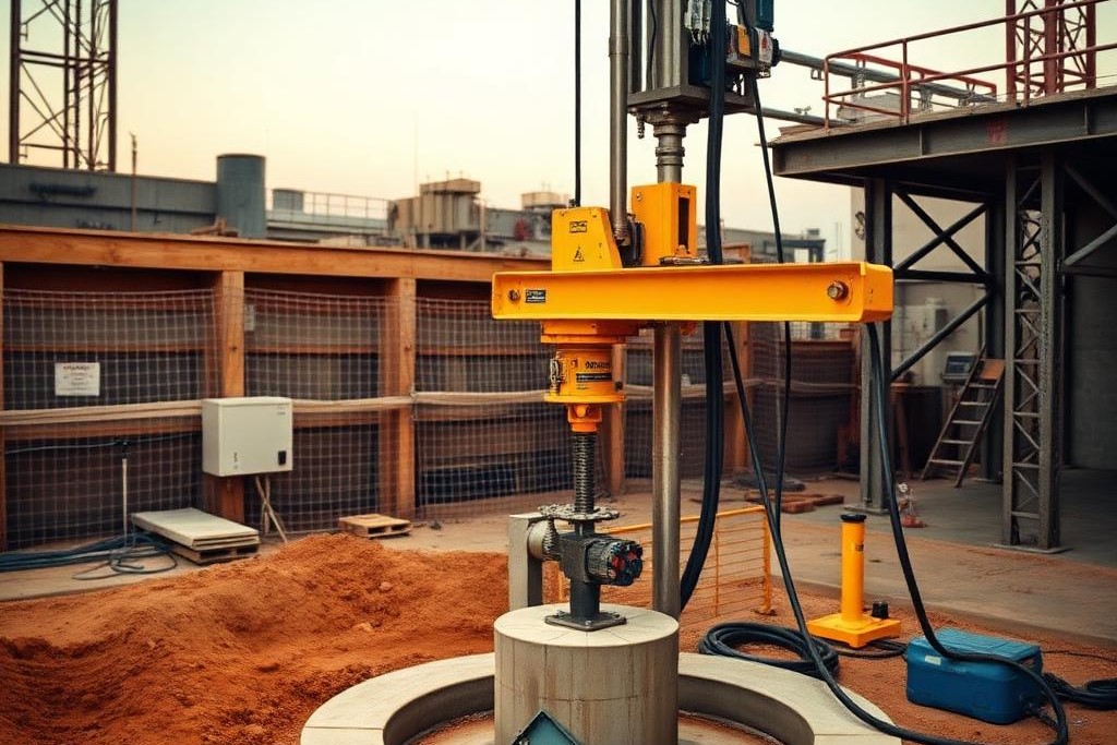
All the engineering, the planning, the heavy iron moving on site—it all comes down to this. The moment of truth for a deep foundation project is often the load test. This is where we intentionally take a perfectly good, multimillion-dollar drilled shaft and try to break it. We apply hundreds, sometimes thousands, of tons of force to a single foundation element, pushing it far beyond the load it will ever see in service. It feels counterintuitive, but it’s the single most important reality check in the entire process. It’s the point where the geotechnical engineer’s design assumptions, born from soil borings and lab tests, get a final, brutal exam against the real-world performance of the foundation we’ve just built.
From Paper to Paydirt: Bridging the Geotechnical Gap
A geotechnical report is the starting point for any drilled shaft design. It’s a snapshot of the subsurface, based on a few small-diameter borings across a large site. From that limited data, the engineer extrapolates the soil and rock properties—friction angles, cohesion, bearing capacity—to design foundations capable of supporting the immense loads of a data center, semiconductor fab, or power plant. But the ground is never as uniform as the report suggests. There are anomalies, pockets of weaker material, and variations in rock quality that the borings might have missed.
The test shaft is the bridge between that theoretical design and the geological reality. It’s typically installed in the location deemed to have the most challenging or representative ground conditions on the site. By testing this one shaft to its limits, we validate the performance criteria for all the other "production" shafts on the project. A successful test proves the design works, not just on paper, but in the actual paydirt a hundred feet below the surface.
This process is fundamental to risk management for the project owner and developer. The foundations are the critical link between the structure and the earth. If they fail, the entire project is compromised. At DrillingCrust Holdings, the operating companies we support are often building foundations for the country’s most critical infrastructure. For the massive columns supporting the U.S. power grid rebuild or the vibration-sensitive floors of an EV battery plant, there is no margin for error. The load test provides the proof of performance that everyone from the structural engineer to the insurance underwriter relies on.
The Two Schools of Static Testing
When it comes to proving a shaft’s capacity, there are two primary methods of static testing: the traditional top-down test and the more modern bi-directional test, often called an Osterberg Cell or O-Cell test. Both aim to answer the same question—how does the shaft behave under load?—but they go about it in completely different ways. The choice between them depends on the project specifics, the magnitude of the test load, site logistics, and cost.
The traditional method is conceptually simple. You build a massive steel reaction frame over the top of the test shaft, load it up with immense weight (called kentledge) or anchor it to other foundations, and use hydraulic jacks to push down on the shaft. Instruments measure the applied load and the corresponding downward displacement at the top. It’s straightforward, and the results are easy to interpret. You get a direct measure of the total foundation performance right at the pile head.
The bi-directional O-Cell test works from the inside out. A specialized, high-capacity hydraulic jack assembly is cast directly into the concrete of the drilled shaft itself, typically near the bottom. When pressurized, the jack pushes upward on the shaft above it, mobilizing skin friction, while simultaneously pushing downward on the portion below, mobilizing end bearing and more skin friction. It effectively splits the shaft into two test segments. This method can apply enormous test loads without the need for a cumbersome reaction frame on the surface.
A Project Within a Project: Top-Down Test Setup
Executing a top-down static load test is a major construction effort in its own right. The first step is building the reaction system. If reaction piles are used, these are often production shafts themselves, positioned to surround the central test shaft. The drilling contractor has to install these with the same precision as any other foundation element. A heavy steel reaction frame, consisting of massive I-beams, is then assembled over the test shaft and connected to the reaction piles.
This setup requires significant logistical support. Our operating partners use equipment like the JLG 2733 telehandlers to lift and position the steel beams, which can weigh many tons each. Western Star 49X tractors are busy for days, hauling the beams, jacks, and instrumentation trailers to the site. The entire test area becomes a restricted zone, requiring careful coordination with all other site activities. The setup alone can take a week or more before any testing can even begin.
Once the frame is secure, hydraulic jacks are placed between the frame and the pile top, and a calibrated load cell is installed to measure the force. A separate reference frame is erected around the pile head, holding dial gauges or electronic displacement transducers that measure the shaft’s movement to the thousandth of an inch. It’s a slow, methodical process that requires a specialized testing contractor, but the drilling contractor’s role is critical in providing access and support.
The Elegant Alternative: Bi-Directional O-Cell Testing
The O-Cell method offers a more elegant, if complex, solution. The real work happens long before the test itself. The drilling contractor, working with the testing firm, has to carefully lower the O-Cell assembly, along with attached strain gauges and pipes for the hydraulic fluid, into the rebar cage before it’s placed in the hole. This requires skill and precision; the assembly is expensive and the instrumentation is sensitive. Our crews might use a Cat 308 excavator with a sling to gently guide the cage and O-Cell into the shaft.
Once the shaft is poured and the concrete has cured, the test can begin. Hydraulic lines running to the surface are connected to a pump. As the pressure increases, the jack expands. What’s brilliant about this method is that the shaft itself provides its own reaction. The upward force is resisted by the skin friction along the upper part of the shaft, and the downward force is resisted by the end bearing and skin friction on the lower part.
This allows for testing shafts to much higher capacities than is often practical with a top-down setup. Generating 6,000 tons of reaction force with surface kentledge is a monumental task; an O-Cell can be designed to do it with relative ease. The trade-off is that you get two separate measurements—upward and downward—that must be combined and interpreted to construct an equivalent top-down load curve.
Interpreting the Curves: The Language of Load Tests
The final output of a load test is a graph plotting load versus displacement. This curve is the foundations resume; it tells the entire story of its performance. In a top-down test, the engineer is looking for a stable response. As the load is applied in increments, the shaft moves downward. It should reach a point of equilibrium at each load step. If the displacement continues to increase without any additional load—a phenomenon called creep—it can be a sign of impending failure.
A "pass" is typically defined by a set of criteria agreed upon beforehand. For example, the specification might state that the net displacement at the maximum design load shall not exceed half an inch. A successful test shows the shaft moving a small, predictable amount and then stabilizing. A plunging failure is unmistakable: the curve on the graph goes vertical as the shaft begins sinking into the ground with no ability to resist more load. That is a clear and catastrophic "fail."
With O-Cell tests, the data is more complex. You get two curves, one for the upward movement and one for the downward movement. Strain gauges placed along the length of the rebar cage provide even more detail, showing the engineer exactly how the load is being transferred from the concrete to the surrounding soil or rock at different depths. This detailed data allows for a much more optimized design, potentially allowing the engineer to shorten the production shafts, saving the owner considerable money and time.
When Good Shafts Go Bad: The Anatomy of a Failure
A failed load test is one of the most stressful events on a construction project. It immediately triggers a cascade of questions and a frantic search for the cause. The first suspect is always the ground. Did the test shaft encounter a geological anomaly, like a soft clay seam or a void in the rock, that the initial borings missed? This is why the drilling contractor’s own logs, recorded by an experienced operator on a rig like our CZM LR160, are so important. They provide a high-resolution record of the drilling resistance, which can later be compared to the test results.
However, the failure isn’t always in the design or the geology. The cause can sometimes be found in the construction of the test shaft itself. If the concrete was contaminated, if a slurry-supported hole was not cleaned properly, or if a void was created during the concrete pour, the test shaft will not be representative of the production shafts. This is a false failure, and it highlights the immense responsibility on the drilling contractor to ensure the test shaft is their absolute best work.
This is where a company’s culture of quality becomes its best defense. The operating companies we partner with understand that meticulous documentation, from concrete tickets to drilling logs to post-pour inspection reports, is not just paperwork. It is the evidence that proves the work was done to specification. In the high-stakes aftermath of a failed test, having a clear, unimpeachable record of construction quality is the only thing that separates fact from blame.
The Ripple Effect: Schedule and Cost Consequences
The financial and schedule implications of a failed test are immense. Work on all subsequent production shafts often comes to an immediate halt. The engineering team must go back to the drawing board. A redesign could involve making the shafts longer, wider, or increasing the total number of shafts. It could even mean abandoning drilled shafts altogether in favor of a completely different foundation system.
This is not a quick fix. A redesign triggers a new round of permitting and approvals. New materials, such as longer rebar cages or different concrete mixes, must be ordered. The drilling contractor, who may have been planning to demobilize, now has their schedule thrown into uncertainty. A six-week delay on a critical path activity like deep foundations is not uncommon. For the owner of a new data center, that six-week delay can translate into tens of millions of dollars in lost revenue and market opportunity.
This domino effect impacts everyone. The general contractor’s entire site logistics plan is disrupted. The concrete supplier, the rebar fabricator, and the trucking companies all have to adjust. It underscores why DrillingCrust focuses on providing top-tier, reliable equipment. When our operating partners are faced with a challenge, the last thing they need to worry about is whether their rig, loader, or truck is up to the task of executing the recovery plan.
The Driller’s Role: More Than Making a Hole
The drilling contractor’s responsibility extends far beyond simply excavating a hole to the right depth and diameter. During a load test program, they become a central logistical player. They must ensure the test shaft is constructed flawlessly, often under heightened scrutiny from the owner’s representatives, the geotechnical engineer, and third-party inspectors. Every step, from mixing the drilling polymer to placing the rebar cage, must be perfect.
Our partners are responsible for coordinating access for the testing contractor, clearing and grading the area, and providing support for the setup. This can involve using a Cat 299D3 track loader to move materials or a Ford F-450 work truck to run errands for the specialized testing crew. They are accountable for maintaining a safe, secure perimeter around the test, which can be under extreme hydraulic pressure for days at a time.
Ultimately, the contractor’s execution and documentation are what stand behind the validity of the test. A successful load test is a shared victory for the entire team, validating the work of the designer and the builder. It provides the confidence needed to proceed with the rest of the project’s foundations. It’s a high-pressure, high-stakes part of the job, but it’s the bedrock of quality assurance in the world of heavy commercial construction. It’s where intent meets reality.
On many large drilled shaft projects, the final act of the drilling contractor's scope is a load test. It is the moment the engineering assumptions get compared against the real behavior of the finished foundation.
What a load test measures
Static load tests apply a controlled load to a completed shaft — often several times the design load — and measure how the shaft responds. Instrumentation captures displacement at the top and, where installed, strain along the length of the shaft. The results tell the engineer whether the shaft is behaving as designed and whether production shafts on the project can be safely used at their intended capacity.
Why testing matters for the project
A successful load test allows the design team to sign off on production shafts. A failed one triggers redesign — longer shafts, more shafts, or different foundation geometry — with schedule and cost consequences for everyone involved. Getting the first test right is not a small thing.
Contractor responsibilities
Load testing is a team sport. The drilling contractor installs the test shaft to the same standard as production work, coordinates access for the testing crew, and often supports instrumentation installation. Executing that well protects the entire project schedule.
Working in commercial drilling?
Reach out to a DrillingCrust representative to talk projects, partnerships, or the fleet.

A holding company operating across the U.S. commercial drilling industry. We invest capital, provide funding, and lease equipment to established operators building the foundations of modern American infrastructure.
Contact
© 2026 DrillingCrust Holdings LLC. All rights reserved.