
Rebar Cages: Fabrication, Handling, and Why They Drive Schedule
April 10, 2026 · 6 min read · By Thomas Charles
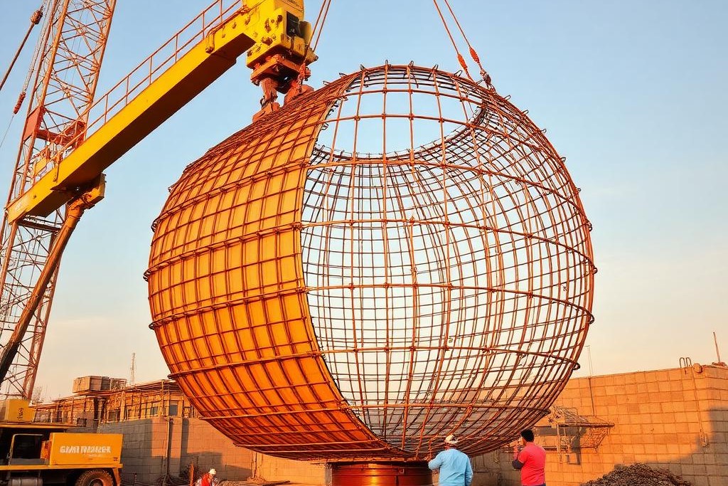
For all the attention a six-figure drill rig gets, the real governor on a drilled shaft project is often a twisted bundle of steel and wire. A drilled shaft is an engineered composite. The concrete provides compressive strength, but the rebar cage inside it provides the tensile strength. Without that cage, precisely built and correctly placed, you just have a deep hole filled with weak, unreinforced concrete. Newcomers to the industry are often surprised to learn that we spend as much time—or more—planning, fabricating, and handling these cages as we do turning the auger. The drilling is the dramatic part, but the cage is what dictates the pace of the entire operation. When a project goes off the rails, it’s rarely because the rig can’t drill. It’s often because a cage wasn’t ready, wouldn’t fit, or got wrecked on its way into the hole.
The Anatomy of a Drilled Shaft Cage
At a glance, a rebar cage looks like a simple cylinder of steel bars. The reality is that it’s a complex, precisely engineered structure. The main vertical bars, or longitudinal bars, are the backbone. Their size and grade are specified by the structural engineer to handle the primary tensile loads on the foundation. For a drilled shaft supporting a major transmission line or a data center column, these can be massive, sometimes #18 bars, which are over two inches in diameter. Surrounding these vertical bars are hoops or a continuous spiral of smaller-diameter rebar. This containment steel serves several purposes: it holds the longitudinal bars in place during the concrete pour, provides shear resistance, and confines the concrete core, increasing its strength and ductility. The spacing of these hoops is critical; it’s often tighter at the top and bottom of the cage where forces are concentrated.
Then you have the spacers, often called centralizers or "spiders." These are plastic or steel wheels attached to the outside of the cage. Their sole job is to guarantee a minimum distance between the steel cage and the wall of the borehole. This "concrete cover" is not just a token gap. It’s a vital layer of protection that prevents moisture and soil contaminants from reaching the steel, which would cause it to rust and expand, cracking the shaft from the inside out. On a five-foot diameter shaft, the engineer might specify three inches of cover. Without properly designed and installed centralizers, the sheer weight of the cage can cause it to lean against the side of the excavation, resulting in zero cover on one side and excessive cover on the other. This is a non-conformance that can, in severe cases, lead to the rejection of the entire shaft.
Consider a typical cage for a 6-foot diameter, 80-foot deep shaft for a new semiconductor fab. It might have twenty #14 longitudinal bars and a #6 spiral at 6-inch spacing. That cage will weigh over 30,000 pounds and be flimsy and flexible for its length. The fabrication drawings for a single cage can run to several pages, specifying not just the bar sizes and spacing, but also the exact locations of lap splices, the type of wire ties to be used (and how many per intersection), the placement of heavy-duty lifting eyes, and the positions for permanent casing spacers. It is a detailed, prescriptive assembly, and any deviation can have significant structural—and financial—consequences.
Fabrication: Where Theory Meets Mud and Steel
Cages are typically built in a dedicated laydown yard adjacent to the main drilling operation. This work is a specialty in itself, usually handled by a team of ironworkers. The process starts with building a template or jig on the ground to hold the main longitudinal bars in the correct circular pattern. The bars, which can be 60 feet long or more, are maneuvered into place, and then the crew begins tying the hoops or spiral. This is hard, physical labor. Every intersection of a longitudinal bar and a hoop must be secured with tie wire, using special hand tools. For a large cage, this can mean thousands of individual ties.
Attention to detail here is paramount. A crew that rushes the job, using too few ties or not securing them properly, is building a "soft" cage. A soft cage is prone to deforming under its own weight. When the crane picks it, the cage can rack into a parallelogram or "bird-cage," where the middle section bulges out and the ends suck in. Once a cage has bird-caged, it’s nearly impossible to straighten. It won’t fit into the borehole, and the carefully specified clearances will be lost. This often means the entire cage has to be disassembled and rebuilt, a catastrophic delay that can cost a full day or more of production.
This is also where design clashes with reality. The engineer’s drawings are perfect, two-dimensional representations. The laydown yard is a muddy, uneven construction site. The ironworkers have to translate the clean lines on the page into a three-dimensional steel structure that can be picked, flown, and placed in a hole full of slurry. This requires experience and judgment. For example, they might add temporary bracing inside the cage to keep it rigid during the lift, which then has to be cut out just before it’s lowered into the shaft. This isn’t on the drawings; it’s part of the field craft that separates a professional crew from a group of amateurs.
The Critical Path: Laydown to Borehole
Once the cage is built, inspected, and signed off, the critical sequence of handling begins. This is a carefully choreographed maneuver that involves multiple pieces of equipment and clear communication. First, the cage needs to be moved from the fabrication area to the drill site. A JLG 2733 telehandler might be used to get under one end, while a Cat 308 excavator with a hydraulic thumb grabs the other. They carefully walk the cage into position next to the open borehole.
The main lift is handled by a large service crane. The rigging is critical. Using a single-point pick on a long, heavy cage is a recipe for disaster. A spreader bar is almost always required to provide at least two, and sometimes four, pick points along the length of the cage. This distributes the load and minimizes the bending that can lead to buckling or bird-caging. The crane operator, the riggers on the ground, and the drill crew have to work as one. The lift has to be slow and steady, with taglines used to control any rotation.
As the cage is lifted vertical, it’s guided over the open hole. The excavator might be used to help "stab" the bottom of the cage into the top of the casing. Then begins the slow process of lowering the cage into the shaft, which is often full of drilling fluid or polymer slurry. The centralizers scrape against the sides of the temporary steel casing at the top of the hole. If one of them breaks off, it can fall to the bottom of the hole, potentially preventing the cage from reaching its full design depth. Getting it back out is a nightmare. This entire process, from the laydown yard to the bottom of the hole, can easily take an hour or more, and that’s when everything goes right.
Splicing Cages for Deep Shafts
For shafts deeper than 60 or 70 feet, it’s often impractical or impossible to build and handle the cage in a single piece. In these cases, the cage is fabricated in two or more sections that are spliced together at the drill site. The lower section is lifted and partially lowered into the borehole, then temporarily hung off from the top of the steel casing. The upper section is then lifted and positioned directly over the lower one.
The ironworkers then have to connect them. This is done by lap splicing, where the vertical bars of the top section overlap with the protruding bars of the lower section. The length of this lap is specified by the engineer—it can be several feet—and every single bar has to be securely connected. This can be done with mechanical couplers, which are threaded sleeves that join the bars end-to-end, or by physically wiring the lapped bars together. This is precarious work, often done from a man basket suspended over the open hole. It is slow, methodical, and a single missed connection can compromise the entire structural integrity of the foundation. A splice on a large-diameter shaft can add two to three hours to the cycle time for a single pour.
The Ripple Effect of a Delayed Pour
A problem with a rebar cage doesn’t just cause a localized delay. It sends a shockwave through the entire project schedule. The concrete for a drilled shaft pour is a perishable product, ordered for a specific time. If the cage gets damaged during the lift, that concrete truck, or a whole fleet of them, is now waiting. The batch plant might have to dump the material, a cost that gets charged back to the project. The driller’s clock is always ticking; a CZM LR160 rig and its crew cost thousands of dollars per day, whether they are drilling or standing around watching ironworkers rebuild a busted cage.
A half-day delay sounds minor, but it means a shaft that was supposed to be poured on Tuesday morning now has to wait until the afternoon, or maybe even Wednesday. This can create a domino effect, pushing back the schedule for subsequent shafts, idling the pump truck and concrete finishing crew, and disrupting the entire flow of the site. On a high-production job, where the goal is to drill and pour a shaft every single day, a single cage failure can throw the whole week’s schedule into chaos. This is why the seemingly mundane task of cage fabrication and handling receives so much focus from the management team. It is the single biggest variable and the most common source of lost production.
The Fleet is the Foundation
This brings us to a fundamental truth of the commercial drilling business: the rig is just one piece of the puzzle. A productive operation is a complete system, a fleet of support equipment that enables the rig to do its job efficiently. You cannot achieve high production rates if the critical path is constantly being choked by cage handling. This is why our operating companies pair a powerful rig like the CZM LR160 with a versatile fleet of support iron. A Cat 299D3 XE track loader is indispensable for moving rebar, tools, and consumables around the laydown yard. A Cat 308 excavator isn’t just for digging sumps; its hydraulic thumb makes it the perfect tool for safely grabbing, positioning, and guiding heavy cages.
The JLG 2733 telehandler can reach over obstacles to lift materials, and our Western Star tractors and lowboy trailers ensure that casing, rebar, and equipment arrive on site and get moved into position without delay. It’s this combination of the right drilling rig and the right support fleet that turns cage handling from a high-risk bottleneck into a routine, repeatable process. When the system works, the rebar cage is ready the moment the hole is clean, it flies into place without drama, and the concrete trucks can roll in on schedule. That is how you make money in the drilling business. It’s not just about making a hole; it’s about building a foundation, and that starts with the steel.
For anyone new to commercial drilling, it can be surprising how much of the work revolves around the rebar cage rather than the drilling itself. A modern drilled shaft is a composite structure — the steel cage and the concrete are engineered to work together — and the cage often ends up driving the schedule.
Fabrication realities
Large cages are heavy, awkward, and precisely detailed. They are typically assembled off-site or in a laydown yard, with hoop steel tied around longitudinal bars, spacers positioned to guarantee concrete cover, and lifting points designed to keep the cage from deforming when it is picked.
Handling on site
Getting the cage from the laydown yard into the hole without damaging it takes coordination between the crane operator, the drill crew, and the ironworkers. A cage that racks or buckles during lifting can delay a pour by half a day — and cost the project real money.
Why fleet composition matters
This is one of the many reasons a drilling rig alone does not make a productive operation. A support excavator with a hydraulic thumb, a track loader, and the right rigging are what turn cage handling from a bottleneck into a routine step. It is the fleet, not just the rig, that keeps drilled shaft production moving.
Working in commercial drilling?
Reach out to a DrillingCrust representative to talk projects, partnerships, or the fleet.

A holding company operating across the U.S. commercial drilling industry. We invest capital, provide funding, and lease equipment to established operators building the foundations of modern American infrastructure.
Contact
© 2026 DrillingCrust Holdings LLC. All rights reserved.